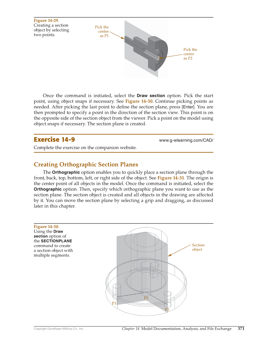
Copyright Goodheart-Willcox Co., Inc. Chapter 14 Model Documentation, Analysis, and File Exchange 371 Once the command is initiated, select the Draw section option. Pick the start point, using object snaps if necessary. See Figure 14-30. Continue picking points as needed. After picking the last point to defi ne the section plane, press [Enter]. You are then prompted to specify a point in the direction of the section view. This point is on the opposite side of the section object from the viewer. Pick a point on the model using object snaps if necessary. The section plane is created. Exercise 14-9 www.g-wlearning.com/CAD/ Complete the exercise on the companion website. Creating Orthographic Section Planes The Orthographic option enables you to quickly place a section plane through the front, back, top, bottom, left, or right side of the object. See Figure 14-31. The origin is the center point of all objects in the model. Once the command is initiated, select the Orthographic option. Then, specify which orthographic plane you want to use as the section plane. The section object is created and all objects in the drawing are affected by it. You can move the section plane by selecting a grip and dragging, as discussed later in this chapter. Pick the center as P1 Pick the center as P2 Figure 14-29. Creating a section object by selecting two points. Section object P3 P1 P2 Figure 14-30. Using the Draw section option of the SECTIONPLANE command to create a section object with multiple segments.