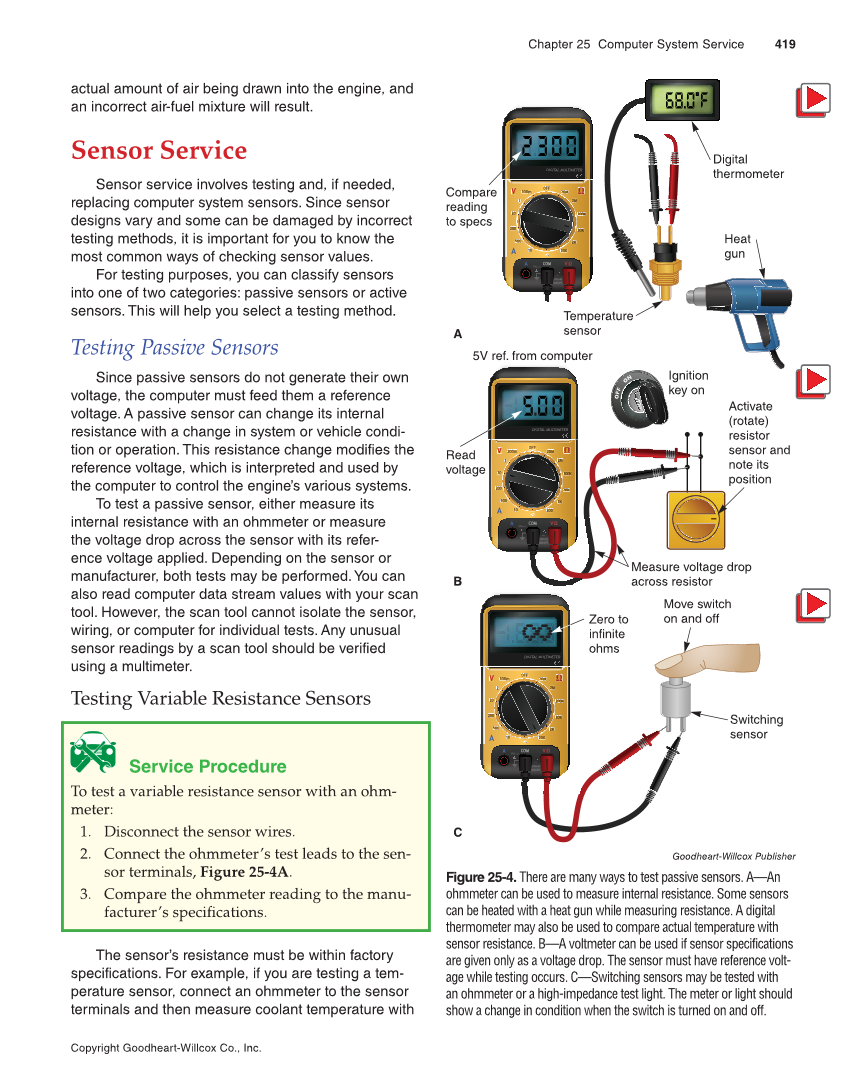
Chapter 25 Computer System Service 419 Copyright Goodheart-Willcox Co., Inc. actual amount of air being drawn into the engine, and an incorrect air-fuel mixture will result. Sensor Service Sensor service involves testing and, if needed, replacing computer system sensors. Since sensor designs vary and some can be damaged by incorrect testing methods, it is important for you to know the most common ways of checking sensor values. For testing purposes, you can classify sensors into one of two categories: passive sensors or active sensors. This will help you select a testing method. Testing Passive Sensors Since passive sensors do not generate their own voltage, the computer must feed them a reference voltage. A passive sensor can change its internal resistance with a change in system or vehicle condi- tion or operation. This resistance change modifies the reference voltage, which is interpreted and used by the computer to control the engine’s various systems. To test a passive sensor, either measure its internal resistance with an ohmmeter or measure the voltage drop across the sensor with its refer- ence voltage applied. Depending on the sensor or manufacturer, both tests may be performed. You can also read computer data stream values with your scan tool. However, the scan tool cannot isolate the sensor, wiring, or computer for individual tests. Any unusual sensor readings by a scan tool should be verified using a multimeter. Testing Variable Resistance Sensors Service Procedure To test a variable resistance sensor with an ohm- meter: 1. Disconnect the sensor wires. 2. Connect the ohmmeter’s test leads to the sen- sor terminals, Figure 25-4A. 3. Compare the ohmmeter reading to the manu- facturer’s specifications. The sensor’s resistance must be within factory specifications. For example, if you are testing a tem- perature sensor, connect an ohmmeter to the sensor terminals and then measure coolant temperature with OFF 2 200 m DIGITAL MULTIMETER 2 20 2 200 0 10A MAX MAX MAX 600 AC 600mAC 0mAC 600mDC 600mDC 10 COM 500 2 200 2K 20K 0K 200K 00 2M 20M 2 V Ω Ω VΩ A A OFF 2 200 m DIGITAL MULTIMETER 2 20 2 200 0 10A MAX MAX MAX 600mAC 600mAC 600mDC 600mDC 10 COM 500 200 2 2K 20K 0K 200K 00 2M 20M 2 V Ω Ω VΩ A A OFF 2 200 m DIGITAL MULTIMETER 2 2 20 200 0 10A MAX MAX MAX 600 AC 600mAC 0mAC 600mDC 600mDC 10 COM 500 2 200 2K 20K 0K 200K 0 2M 2 20 M V Ω Ω VΩ A A Digital thermometer Temperature sensor Compare reading to specs Heat gun A 5V ref. from computer Read voltage Activate (rotate) resistor sensor and note its position Measure voltage drop across resistor Ignition key on B Switching sensor Zero to infinite ohms Move switch on and off C Goodheart-Willcox Publisher Figure 25-4. There are many ways to test passive sensors. A—An ohmmeter can be used to measure internal resistance. Some sensors can be heated with a heat gun while measuring resistance. A digital thermometer may also be used to compare actual temperature with sensor resistance. B—A voltmeter can be used if sensor specifications are given only as a voltage drop. The sensor must have reference volt- age while testing occurs. C—Switching sensors may be tested with an ohmmeter or a high-impedance test light. The meter or light should show a change in condition when the switch is turned on and off.