)
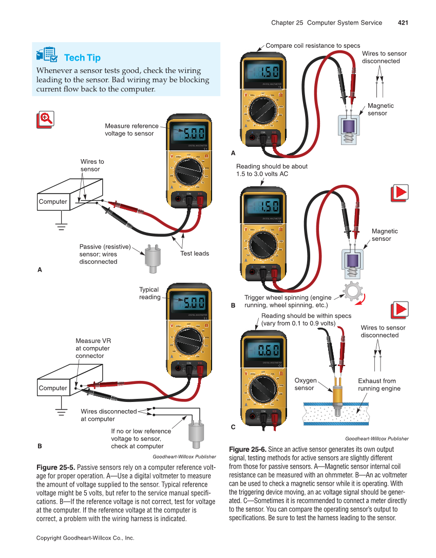
Chapter 25 Computer System Service 421 Copyright Goodheart-Willcox Co., Inc. Tech Tip Whenever a sensor tests good, check the wiring leading to the sensor. Bad wiring may be blocking current flow back to the computer. OFF 2 200 m DIGITAL MULTIMETER 2 20 2 20 00 10A MAX MAX MAX 600mAC 600mAC 600mDC 600mDC 10 COM 500 2 200 2K 20K 0K 200K 00 2M 20M 2 V Ω VΩ A A OFF 2 200 m DIGITAL MULTIMETER 2 2 20 20 00 10A MAX MAX MAX 600mAC 600mAC 600mDC 600mDC 10 COM 500 200 2 2K 20K 0K 200K 00 2M 20M 2 V Ω VΩ A A Measure reference voltage to sensor Wires to sensor Computer Test leads Passive (resistive) sensor wires disconnected A Typical reading Wires disconnected at computer Measure VR at computer connector If no or low reference voltage to sensor, check at computer B Computer Goodheart-Willcox Publisher Figure 25-5. Passive sensors rely on a computer reference volt- age for proper operation. A—Use a digital voltmeter to measure the amount of voltage supplied to the sensor. Typical reference voltage might be 5 volts, but refer to the service manual specifi- cations. B—If the reference voltage is not correct, test for voltage at the computer. If the reference voltage at the computer is correct, a problem with the wiring harness is indicated. OFF 2 200m DIGITAL MULTIMETER 2 20 2 200 0 10AMAX MAX MAX 600mAC 600mAC 600mDC 600mDC 10 COM 500 2 200 2K 20K 0K 200K 0 K 2M 20M 2 V Ω Ω VΩ A A OFF 2 200m DIGITAL MULTIMETER 2 2 20 200 0 10AMAX MAX MAX 600mAC 600mAC 600mDC 600mDC 10 COM 500 2 200 2K 20K 0K 20 00K K 2M 2 20 M V Ω Ω VΩ A A OFF 2 200 m DIGITAL MULTIMETER 2 2 20 20 00 10A MAX MAX MAX 600mAC 600mAC 600mDC 600mDC 10 COM 500 2 200 2K 20K 0K 200K 00 2M 2 20 M V Ω Ω VΩ A A Wires to sensor disconnected Magnetic sensor Compare coil resistance to specs A B C Magnetic sensor Trigger wheel spinning (engine running, wheel spinning, etc.) Reading should be about 1.5 to 3.0 volts AC Oxygen sensor Exhaust from running engine Reading should be within specs (vary from 0.1 to 0.9 volts) Wires to sensor disconnected Goodheart-Willcox Publisher Figure 25-6. Since an active sensor generates its own output signal, testing methods for active sensors are slightly different from those for passive sensors. A—Magnetic sensor internal coil resistance can be measured with an ohmmeter. B—An ac voltmeter can be used to check a magnetic sensor while it is operating. With the triggering device moving, an ac voltage signal should be gener- ated. C—Sometimes it is recommended to connect a meter directly to the sensor. You can compare the operating sensor’s output to specifications. Be sure to test the harness leading to the sensor.