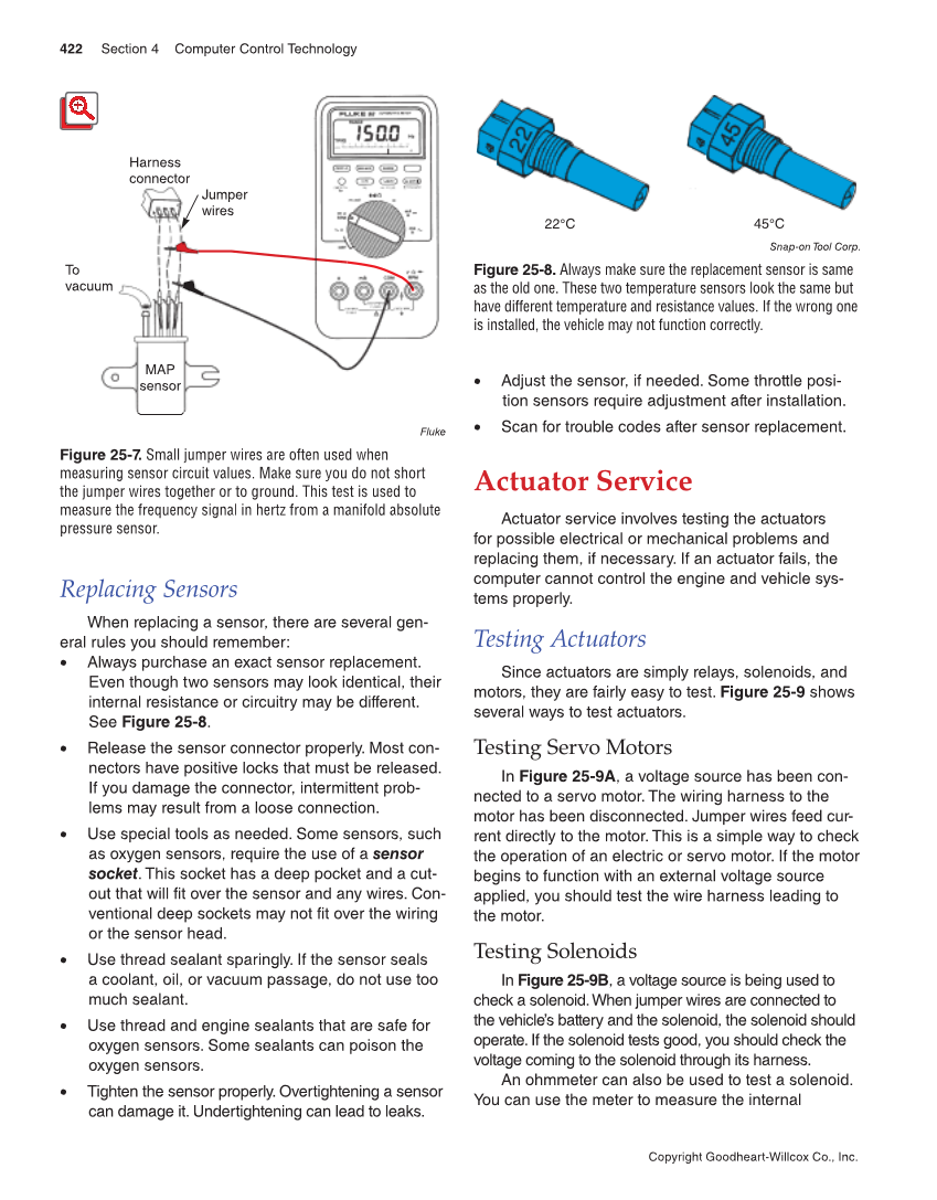
422 Section 4 Computer Control Technology Copyright Goodheart-Willcox Co., Inc. Replacing Sensors When replacing a sensor, there are several gen- eral rules you should remember: • Always purchase an exact sensor replacement. Even though two sensors may look identical, their internal resistance or circuitry may be different. See Figure 25-8. • Release the sensor connector properly. Most con- nectors have positive locks that must be released. If you damage the connector, intermittent prob- lems may result from a loose connection. • Use special tools as needed. Some sensors, such as oxygen sensors, require the use of a sensor socket. This socket has a deep pocket and a cut- out that will fit over the sensor and any wires. Con- ventional deep sockets may not fit over the wiring or the sensor head. • Use thread sealant sparingly. If the sensor seals a coolant, oil, or vacuum passage, do not use too much sealant. • Use thread and engine sealants that are safe for oxygen sensors. Some sealants can poison the oxygen sensors. • Tighten the sensor properly. Overtightening a sensor can damage it. Undertightening can lead to leaks. • Adjust the sensor, if needed. Some throttle posi- tion sensors require adjustment after installation. • Scan for trouble codes after sensor replacement. Actuator Service Actuator service involves testing the actuators for possible electrical or mechanical problems and replacing them, if necessary. If an actuator fails, the computer cannot control the engine and vehicle sys- tems properly. Testing Actuators Since actuators are simply relays, solenoids, and motors, they are fairly easy to test. Figure 25-9 shows several ways to test actuators. Testing Servo Motors In Figure 25-9A, a voltage source has been con- nected to a servo motor. The wiring harness to the motor has been disconnected. Jumper wires feed cur- rent directly to the motor. This is a simple way to check the operation of an electric or servo motor. If the motor begins to function with an external voltage source applied, you should test the wire harness leading to the motor. Testing Solenoids In Figure 25-9B, a voltage source is being used to check a solenoid. When jumper wires are connected to the vehicle’s battery and the solenoid, the solenoid should operate. If the solenoid tests good, you should check the voltage coming to the solenoid through its harness. An ohmmeter can also be used to test a solenoid. You can use the meter to measure the internal MAP sensor Jumper wires Harness connector To vacuum Fluke Figure 25-7. Small jumper wires are often used when measuring sensor circuit values. Make sure you do not short the jumper wires together or to ground. This test is used to measure the frequency signal in hertz from a manifold absolute pressure sensor. 22°C 45°C Snap-on Tool Corp. Figure 25-8. Always make sure the replacement sensor is same as the old one. These two temperature sensors look the same but have different temperature and resistance values. If the wrong one is installed, the vehicle may not function correctly.