)
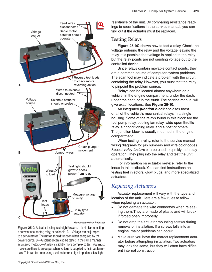
Chapter 25 Computer System Service 423 Copyright Goodheart-Willcox Co., Inc. resistance of the unit. By comparing resistance read- ings to specifications in the service manual, you can find out if the actuator must be replaced. Testing Relays Figure 25-9C shows how to test a relay. Check the voltage entering the relay and the voltage leaving the relay. It is possible that voltage is applied to the relay but the relay points are not sending voltage out to the controlled device. Since relays contain movable contact points, they are a common source of computer system problems. The scan tool may indicate a problem with the circuit containing the relay. However, you must test the relay to pinpoint the problem source. Relays can be located almost anywhere on a vehicle: in the engine compartment, under the dash, under the seat, or in the trunk. The service manual will give exact locations. See Figure 25-10. An integrated junction block encloses most or all of the vehicle’s mechanical relays in a single housing. Some of the relays found in this block are the fuel pump relay, cooling fan relay, wide open throttle relay, air conditioning relay, and a host of others. The junction block is usually mounted in the engine compartment. When testing a relay, refer to the service manual wiring diagrams for pin numbers and wire color codes. Special relay testers can be used to quickly test relay operation. They plug into the relay and test the unit automatically. For information on actuator service, refer to the index in this textbook. You can find instructions on testing fuel injectors, glow plugs, and more specialized actuators. Replacing Actuators Actuator replacement will vary with the type and location of the unit. Here are a few rules to follow when replacing an actuator. • Do not damage the wire connectors when releas- ing them. They are made of plastic and will break if forced open improperly. • Do not drop the actuator mounting screws during removal or installation. If a screws falls into an engine, major problems can occur. • Make sure you have the correct replacement actu- ator before attempting installation. Two actuators may look the same, but they will often have differ- ent internal construction. Measure voltage to relay Voltage source Feed wires disconnected Servo motor actuator should operate Reverse test leads to check motor reversing action Solenoid actuator should energize Jumper wires Check plunger movement Test light should glow to check power from relay Wires to load Relay type actuator A Voltage source B C Test leads Wires to solenoid disconnected Goodheart-Willcox Publisher Figure 25-9. Actuator testing is straightforward. It is similar to testing a conventional motor, relay, or solenoid. A—Voltage can be jumped to a servo motor. The motor should function when energized by the power source. B—A solenoid can also be tested in the same manner as a servo motor. C—A relay is slightly more complex to test. You must make sure there is an output when voltage is supplied to its input termi- nals. This can be done using a voltmeter or a high-impedance test light.