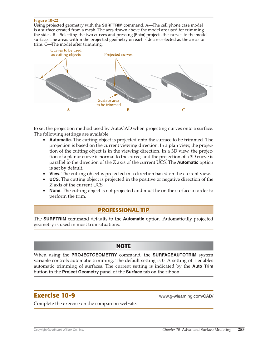
Copyright Goodheart-Willcox Co., Inc. Chapter 10 Advanced Surface Modeling 255 to set the projection method used by AutoCAD when projecting curves onto a surface. The following settings are available. • Automatic. The cutting object is projected onto the surface to be trimmed. The projection is based on the current viewing direction. In a plan view, the projec- tion of the cutting object is in the viewing direction. In a 3D view, the projec- tion of a planar curve is normal to the curve, and the projection of a 3D curve is parallel to the direction of the Z axis of the current UCS. The Automatic option is set by default. • View. The cutting object is projected in a direction based on the current view. • UCS. The cutting object is projected in the positive or negative direction of the Z axis of the current UCS. • None. The cutting object is not projected and must lie on the surface in order to perform the trim. PROFESSIONAL TIP PROFESSIONAL TIP The SURFTRIM command defaults to the Automatic option. Automatically projected geometry is used in most trim situations. NOTE NOTE When using the PROJECTGEOMETRY command, the SURFACEAUTOTRIM system variable controls automatic trimming. The default setting is 0. A setting of 1 enables automatic trimming of surfaces. The current setting is indicated by the Auto Trim button in the Project Geometry panel of the Surface tab on the ribbon. Exercise 10-9 www.g-wlearning.com/CAD/ Complete the exercise on the companion website. Projected curves A B C Surface area to be trimmed Curves to be used as cutting objects Figure 10-22. Using projected geometry with the SURFTRIM command. A—The cell phone case model is a surface created from a mesh. The arcs drawn above the model are used for trimming the sides. B—Selecting the two curves and pressing [Enter] projects the curves to the model surface. The areas within the projected geometry on each side are selected as the areas to trim. C—The model after trimming.