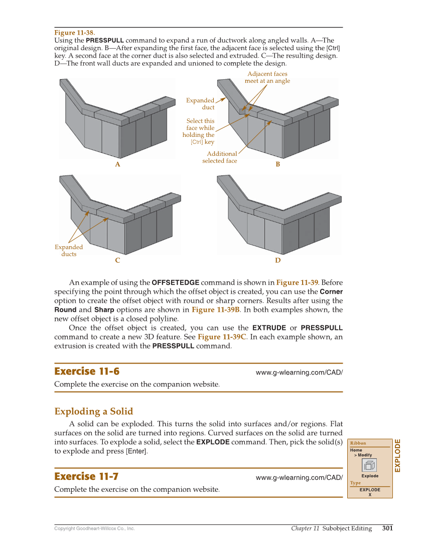
Copyright Goodheart-Willcox Co., Inc. Chapter 11 Subobject Editing 301 An example of using the OFFSETEDGE command is shown in Figure 11-39. Before specifying the point through which the offset object is created, you can use the Corner option to create the offset object with round or sharp corners. Results after using the Round and Sharp options are shown in Figure 11-39B. In both examples shown, the new offset object is a closed polyline. Once the offset object is created, you can use the EXTRUDE or PRESSPULL command to create a new 3D feature. See Figure 11-39C. In each example shown, an extrusion is created with the PRESSPULL command. Exercise 11-6 www.g-wlearning.com/CAD/ Complete the exercise on the companion website. Exploding a Solid A solid can be exploded. This turns the solid into surfaces and/or regions. Flat surfaces on the solid are turned into regions. Curved surfaces on the solid are turned into surfaces. To explode a solid, select the EXPLODE command. Then, pick the solid(s) to explode and press [Enter]. Exercise 11-7 www.g-wlearning.com/CAD/ Complete the exercise on the companion website. EXPLODE Ribbon Home Modify Explode Type EXPLODE X Expanded duct Adjacent faces meet at an angle Select this face while holding the [Ctrl] key Additional selected face A C B D Expanded ducts Figure 11-38. Using the PRESSPULL command to expand a run of ductwork along angled walls. A—The original design. B—After expanding the first face, the adjacent face is selected using the [Ctrl] key. A second face at the corner duct is also selected and extruded. C—The resulting design. D—The front wall ducts are expanded and unioned to complete the design.